Electronics Basics
Electricity is basically the blood flow of machineries. Technology needs electricity to enable its functions and then works on automatically provides faster work on daily activities. We then come up with frequently asked questions, where does this electricity came from and how can we measure it? Well, a power source gives of current. Certain quantities are then measured by the use of a multimeter. A multimeter is an electronic measuring instrument that combines several measurement functions in one unit. There are two categories of multimeters: Analog multimeter and Digital multimeter. These multimeters measure various kinds of quantities of electricity which are typically the appliances that are used in our home. There are three kinds of settings which a multimeter can do. These are the voltmeter, ammeter and the ohmmeter. We will discuss how do we measure the voltage, current and resistance using the multimeters, how Kirchhoff’s rules are applied? , how do these multimeters differ from each other and the limitations of the instruments and the measuring processes
Multimeters
Before using multimeters, one must identify what quantity is to be measured and also we need preparations of the dials, measuring cables, and familiarization with its functions. First thing you need to do is to check if your multimeter is in a good condition, check battery, output screens needs to be functional to read the obtained values to do some measurements. After that an operating procedure needs to be followed:
1. Set dial for the mode of measurement: AC/DC voltage, AC/DC current, AC/DC resistance.
2. Set the proper range. For the Voltage and Current measurements, always use maximum range.
3. Connect measuring cables to their proper terminals. Red for positive terminals and Black for negative terminals. The negative is usually denoted as ground (GND) or COMMON.
4. Zero adjustment setting for Ohmmeters. Adjust needle to zero adjustment by shorting.
5. Ready for measuring voltage, current and resistance.
Voltage Measurements
Voltages can be measured across any points in the circuit. These points refer to the positive terminal and the negative terminal of where the resistor is connected. When current is flowing through the circuit, there exist the potential differences from different points of the circuit. A correct correspondence of the readings depends on the proper connection of the measuring cables and should always be connected from the positive terminal to the negative terminal. The range of the voltmeter should be set to maximum range because we need the correct number of significant figures the meter can give and is used to obtain the voltage across to any points in the circuit. An infinitely large reading of internal resistance can be obtained if the instrument is ideal.

Current Measurements
Current can be measured from a part of a circuit. Such parts include the resistor and the capacitor. An ammeter is inserted in between the two points. Thus wire is disconnected from a connection. This allows the current to absorb the flow passing through the component of the circuit then goes through the ammeter. If an ideal ammeter is used, then a zero internal resistance can be obtained. The measuring cables must be inserted in the proper terminals because if it is inserted across the power source, the measuring needle for the AMM will break because it is very thin. Remember to always use a maximum range setting for proper readings of values.

Resistance Measurements
Resistance is measured by an ohmmeter. Resistors also have color codes which you can obtain the resistance of the resistors by means of nominal values. Resistors from the circuit contain the resistance that we need to measure. Since the resistance of an element is in passive quantity, thus before measuring the resistance of the element, we need to get first the current. No power source is needed in measuring the resistance that is why the internal circuitry contains a battery. Appropriate scales are set in order to obtain the values. The terminals also need to be shorted because of insufficiency of voltage from the battery. This is done by the tips of the measuring cables must touch with each other. Interference can also occur in the set-up so better check if it is properly in place.

Differentiate Digital Multimeter from an Analog Multimeter.
Digital and analog multimeters have many differences in common. The digital MM is more expensive than the analog MM and is much easier to use. The Analog MM displays the measure value by a needle and moves along a scale while a digital MM displays the result directly using 3 or more digits from its screen. The digital MM uses internal power source which is provided by a dry cell. Both multimeters differ in readings because of certain deflections. Although they have many comparisons with each other, the both of them can obtain measured values using different settings from a circuit.
How is Kirchhoff’s rules applied?
A branch point in a network is a point where three or more conductors are joined. A loop is any closed conducting path. Kirchhoff’s rules consist of two following statements: the point rule and the loop rule.
Point rule or junction rule states that the algebraic sum of the currents toward any branch is zero.

The current entering any junction is equal to the current leaving that junction. i1 + i4 = i2 + i3
This law is also called Kirchhoff's point rule, Kirchhoff's junction rule (or nodal rule), and Kirchhoff's first rule.
The principle of conservation of electric charge implies that:
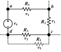
The sum of all the voltages around the loop is equal to zero. v1 + v2 + v3 + v4 = 0
This law is also called Kirchhoff's second law, Kirchhoff's loop (or mesh) rule, and Kirchhoff's second rule.
The principle of conservation of energy implies that the directed sum of the electrical potential differences (voltage) around any closed circuit must be zero.
0 comments